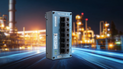
| Switching Layer |
Operates primarily at OSI Layer 2 and forwards Ethernet frames using destination MAC addresses. |
The switch learns source MAC addresses and stores them in a forwarding database. It then sends frames only to the appropriate port when the destination is known. |
Suitable for structured local-area networks, access-layer connectivity, cameras, wireless access points, and VoIP phones. |
| Management |
Common management methods include a web interface, command-line interface, Simple Network Management Protocol, and console access. |
Administrators can configure ports, VLANs, PoE settings, security policies, monitoring, and firmware-related functions instead of relying only on plug-and-play operation. |
Useful when centralized control, troubleshooting, configuration backups, and network visibility are required. |
| Power over Ethernet |
PoE delivers electrical power and data through compatible twisted-pair Ethernet cabling. Supported power levels depend on the IEEE PoE type and switch design. |
The switch detects whether a connected device is PoE-compatible before applying power. It negotiates or classifies the required power and can remove power when the device is disconnected. |
Reduces separate power adapters and electrical outlets for network devices installed on ceilings, poles, walls, or other hard-to-reach locations. |
| PoE Standards |
IEEE 802.3af Type 1: up to 15.4 W at the port
IEEE 802.3at Type 2: up to 30 W at the port
IEEE 802.3bt Type 3: up to 60 W at the port
IEEE 802.3bt Type 4: up to 90 W at the port
|
The available power at the powered device is lower than the switch-port output because cable transmission causes power loss. Actual values depend on the standard, cabling, temperature, and equipment design. |
Select the PoE type according to the device requirement. Higher-power devices may include advanced wireless access points, pan-tilt-zoom cameras, lighting equipment, or digital signage. |
| PoE Power Budget |
The total PoE power budget is the maximum power the switch can provide to all PoE ports at the same time. |
The switch allocates power across ports. If the combined demand exceeds the budget, configured priorities or power-management rules may determine which devices remain powered. |
Calculate simultaneous device demand, startup requirements, future expansion, and an engineering reserve before selecting the switch. |
| VLAN Support |
Common Layer 2 managed features include IEEE 802.1Q tagged VLANs and port-based VLAN assignment. |
VLANs divide one physical switching infrastructure into separate logical broadcast domains. Tags identify VLAN membership across trunk links. |
Separate voice, video, management, guest, and business traffic to improve organization, security, and broadcast control. |
| Traffic Segmentation |
Access ports typically carry traffic for one VLAN, while trunk ports can carry multiple tagged VLANs. |
Traffic is classified according to port configuration and VLAN tags. The switch forwards frames only within the appropriate logical network unless routing is performed elsewhere. |
Important for multi-service networks with cameras, access points, phones, building systems, and administrative devices. |
| Loop Prevention |
Spanning Tree Protocol variants, including STP, RSTP, and sometimes MSTP, may be supported. |
The switch identifies redundant Layer 2 paths and blocks selected links to prevent broadcast storms and continuously circulating frames. A blocked path can be restored when the active path fails. |
Recommended for networks with redundant uplinks, ring topologies, or multiple interconnected switches. Verify compatibility and configuration across all switches. |
| Link Aggregation |
Link Aggregation Control Protocol support may allow multiple physical links to operate as one logical connection. |
Traffic is distributed across member links while the logical connection provides higher aggregate capacity and link redundancy. A failed member link can be removed from service. |
Useful for switch-to-switch uplinks or connections to servers and storage systems, provided both ends support compatible settings. |
| Quality of Service |
QoS may include traffic classification, priority queues, IEEE 802.1p priority markings, rate limiting, and scheduling. |
The switch places selected traffic into higher-priority queues or controls bandwidth to reduce delay, jitter, and congestion. |
Helps protect voice calls, video streams, surveillance traffic, and control data when network links are busy. |
| Multicast Handling |
IGMP snooping may be available for IPv4 multicast traffic, with corresponding multicast-management features depending on the model. |
The switch monitors multicast membership messages and forwards streams only to ports that have requested them, instead of flooding every port. |
Particularly useful for IP video, digital signage, live media distribution, and other one-to-many applications. |
| Port Security |
Possible functions include MAC address limits, sticky MAC learning, MAC filtering, port isolation, and shutdown actions. |
The switch compares observed device addresses with configured rules and can restrict or disable a port when an unauthorized device is detected. |
Use for access control at network outlets, cameras, public-area equipment, and other locations where unauthorized connections are a concern. |
| Storm Control |
Broadcast, multicast, or unknown-unicast rate limiting may be configurable per port. |
The switch monitors traffic rates and limits excessive frame types to prevent one faulty device or loop from consuming network capacity. |
Useful in large access networks and environments containing unmanaged devices, embedded systems, or long cable runs. |
| PoE Monitoring |
Managed PoE switches may display per-port voltage, current, power consumption, PoE status, and fault information. |
The switch measures power delivery and reports abnormal conditions such as overload, short circuit, or unsupported-device detection. |
Simplifies remote troubleshooting and helps identify overloaded ports, failing endpoints, and unexpected power consumption. |
| PoE Scheduling |
Some switches support time-based PoE activation and deactivation. |
Power is supplied according to a configured schedule rather than continuously, while the port remains available for network configuration as supported. |
Can reduce energy use or automatically disable selected cameras, access points, displays, or other devices outside operating hours. |
| Extended-Reach PoE |
Standard Ethernet channel planning commonly uses a maximum channel length of 100 m, including patch leads. Some equipment offers proprietary or special extended-distance modes. |
Extended modes may reduce data rate, alter link negotiation, or require specific cabling and compatible equipment. They should not be assumed to provide standard performance. |
For longer runs, consider fiber uplinks, intermediate switches, PoE extenders, or properly designed remote cabinets instead of relying only on extended modes. |
| Cabling |
Cable category, conductor size, termination quality, ambient temperature, and installation method affect data and PoE performance. |
Electrical resistance causes voltage drop and heat generation. Higher-power PoE installations require careful cable-bundle and temperature planning. |
Use compliant balanced twisted-pair cabling, verify channel length, follow applicable installation standards, and avoid damaged or improperly terminated cables. |
| Uplink Design |
Uplinks may use copper Ethernet, fiber, or a combination of interfaces. Uplink speed can range from standard access rates to multi-gigabit or higher rates. |
Uplinks carry aggregated traffic from access ports to another switch, router, firewall, or core network. Insufficient uplink capacity can create congestion. |
Estimate the simultaneous traffic from cameras, wireless users, phones, and other endpoints before choosing uplink speed and interface type. |
| Network Layer Limitation |
An L2 managed PoE switch generally does not perform full Layer 3 routing unless it specifically includes Layer 3 features. |
Inter-VLAN communication normally requires a router, firewall, or Layer 3 switch. The L2 switch handles local VLAN forwarding but does not automatically route between VLANs. |
Confirm whether the design needs static routing, dynamic routing, DHCP relay, or inter-VLAN routing before selecting an L2-only model. |
| Common Deployment Areas |
Typical environments include offices, schools, hotels, retail sites, warehouses, transportation facilities, security systems, and building automation networks. |
One managed switch can connect endpoints and supply power while VLANs, QoS, security controls, and monitoring organize the traffic. |
The best fit is an access-layer location where many powered Ethernet devices must be connected, managed, and monitored from a central point. |
| Environmental Requirements |
Indoor and industrial models may differ in operating temperature, humidity tolerance, vibration resistance, ingress protection, mounting method, and power-input design. |
The switch must dissipate heat and maintain stable operation within the specified environmental range. PoE load can increase internal temperature. |
For outdoor, industrial, or poorly ventilated locations, check temperature ratings, enclosure requirements, surge protection, grounding, and installation clearance. |
| Redundancy and Reliability |
Relevant options may include redundant power inputs, dual uplinks, spanning-tree support, link aggregation, watchdog functions, and replaceable power supplies. |
Redundant components or paths allow the network to continue operating after selected link, power, or device failures. |
Prioritize redundancy for surveillance, access control, industrial monitoring, emergency communication, and other systems where downtime has a high impact. |
| Selection Checklist |
Evaluate port count, PoE type, total power budget, uplink speed, VLAN capacity, management features, environmental rating, security, warranty, and expansion needs. |
Match the switch specification to current endpoint requirements and include practical capacity for growth, cable loss, peak demand, and operational reserve. |
A properly sized switch improves reliability and avoids common problems such as insufficient power, congested uplinks, unsupported device features, and limited expansion capacity. |